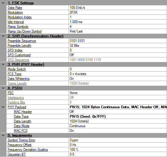
Click in the tree view to display the 802.15.4 SUN FSK setup.
Range: 2.4–400
Default: 100
Enter the data rate of FSK modulation in kb/s. See Table 20-6 and 20-7 in IEEE Std 802.15.4-2015 for details. See also Modulation and coding for 802.15.4 SUN FSK.
When Data Rate or Modulation is changed, Sample Clock is re-calculated.
Choice: 2FSK | 4FSK
Default: 2FSK
Select the FSK modulation level. See Table 20-6 and 20-7 in IEEE Std 802.15.4-2015 for details. See also Modulation and coding for 802.15.4 SUN FSK.
Range: 0.33–2
Default: 1
Enter the modulation index for FSK. See Table 20-6 and 20-7 in IEEE Std 802.15.4-2015 for details. See also Modulation and coding for 802.15.4 SUN FSK.
Range: 0–200 ms
Default: 1.0 ms
Enter the idle interval time in-between frames. When idle interval is set to zero, a continuous waveform will be generated. See 802.15.4 SUN FSK for details.
Range: 1–10
Default: 4
Enter the duration in symbols for waveform ramp up and down. This value is only applied to a burst waveform with non-zero idle interval. See 802.15.4 SUN FSK for details.
Ramp Symbols is only visible and configurable when Idle Interval is not zero.
Choice: First/Last | Center | One | Zero
Default: First/Last
Select the symbol for the period of waveform ramp up and down. See 802.15.4 SUN FSK for details.
|
First/Last |
Use the first data symbol value as the ramp up symbol value and the last data symbol value as the ramp down symbol value. | |
|
Center |
Set the ramp up/down symbol when frequency deviation is zero. | |
|
One |
Set the ramp up/down symbol when frequency deviation is negative. | |
|
Zero |
Set the ramp up/down symbol when frequency deviation is positive. |
Default: 0101 0101
Enter the preamble sequence. The length should be a multiple of 8 for 2FSK and a multiple of 16 for 4FSK.For 4FSK, because the SHR part always uses 2FSK, the input preamble sequence should be the symbol for –fdev or fdev in 4FSK mapping, so only 01 and 11 are allowed.
The preamble length should be the integer multiple of the length of preamble sequence. Therefore, the final preamble field will contain several multiples of the preamble sequence.
Range: 32–8000 for 2FSK; 64–16000 for 4FSK
Default: 32
Enter the preamble length in bits in SHR. It should be integer multiples of the length of preamble sequence. See section 20.2.1.1 in IEEE Std 802.15.4-2015 for details.
Choices: 0 | 1
Default: 0
Enter the index of SFD sequence in SHR. It corresponds to the PIB attribute phySunFskSfd defined in IEEE Std 802.15.4-2015. See section 20.2.1.2 for details.
Choices: On | Off
Default: Off
Enable or disable customized SFD.
If SFD Customized is off, the SFD Sequence is read-only, and is coupled with SFD index and coding on/off.
If SFD Customized is on, the SFD Sequence can be edited. Its length should be 16 for 2FSK and 32 for 4FSK, otherwise it will be truncated or padded with zeros.
For 4FSK, because the SHR part always uses 2FSK, the input SFD sequence should be the symbol for –fdev or fdev in 4FSK mapping, so only 01 and 11 are allowed.
If SFD Customized is off, display the SFD sequence in SHR. This value is read-only and determined by the combination of SFD Index and FEC. See section 20.2.1.2 in IEEE Std 802.15.4-2015 for details. If SFD Customized is on, user can input self-defined SFD sequence.
Choices: 0 | 1
Default: 0
Select whether a normal packet or a mode switch packet will be generated. It will be included in Mode Switch field of PHR. See section 20.2.2 and 20.2.3 in IEEE Std 802.15.4-2015 for details.
|
0 |
Indicates a normal packet that the entire packet shall be transmitted at a single data rate and using a single modulation scheme. | |
|
1 |
Indicates a mode switch packet. If the new mode is 802.15.4 SUN FSK, the packet has the preamble and SFD optional. If the new mode is 802.15.4 SUN OFDM, the packet is the same as 802.15.4 SUN OFDM. |
Choices: 0 = 4-octets | 1 = 2-octets
Default: 0 = 4-octets
Select the FCS type that indicates the transmitted FCS length. It will be included in FCS Type field of PHR. See section 20.2.2 in IEEE Std 802.15.4-2015 for details.
Choices: On | Off
Default: On
Enable or disable the data whitening of PSDU upon transmission. It will be included in Data Whitening field of PHR. See section 20.2.2 in IEEE Std 802.15.4-2015 for details.
Display the total number of octets contained in the PSDU. This value is read-only and automatically updated with PSDU settings and FCS Type. It will be included in Frame Length field of PHR. See section 20.2.2 in IEEE Std 802.15.4-2015 for details.
Choices: None | RSC | NRNSC
Default: None
Select whether FEC is enabled and what type of FEC is used. It corresponds to the PIB attribute phyFSKFECEnabled and phyFskFecScheme defined in IEEE Std 802.15.4-2015. See section 20.3.4 for details.
Choices: On | Off
Default: Off
Select whether interleaving is enabled in conjunction with FEC. Interleaving is always enabled for NRNSC coding and disabled when no FEC is used. In the case of RSC, it corresponds to the PIB attribute phyFskFecInterleavingRsc defined in IEEE Std 802.15.4-2015. See section 20.3.5 for details.
Display the number of padding bits appended to the tail bits, when interleaving is enabled. This value is read-only and automatically updated with PHR and PSDU length. See section 20.3.4 in IEEE Std 802.15.4-2015 for details.
Display the summary of PHY payload configuration.
Click the button on the right to bring up an editor to configure the MAC Header. See Figure 7-1 in IEEE Std 802.15.4-2015 for details.
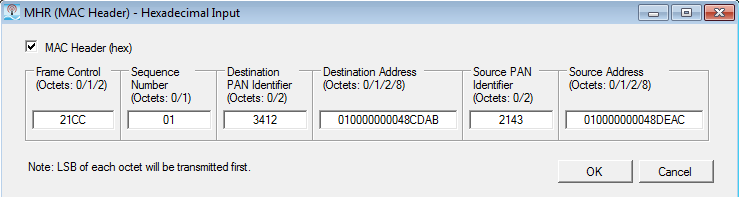
Click the  button on the right to bring up an editor to configure the MAC Header (see the dialog below). See Figure 7-1 in IEEE Std 802.15.4-2015 for details.
You can check the check box to enables pre-pending the MAC header to the data payload. You can set the desired data in each of the individual fields.
You can also disable these fields if the data is no longer desired by clearing the Mac Header (hex) check box.
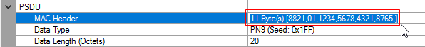
To configure this parameter using .NET API interface, specify the string in the same format, as shown in the GUI. For example, "11 Byte(s) [8821,01,1234,5678,4321,8765,]". To make sure the format is correct, you can highlight and copy the string directly from the parameter field in the GUI, as shown below.
Default: PN9 (Seed: 0x1FF)
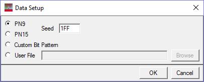
Click in the field, and then the dialog box icon that appears to launch the Data Setup dialog box. In the dialog box, select one of the following data types:
PN9
PN15
Custom Bit Pattern
User File
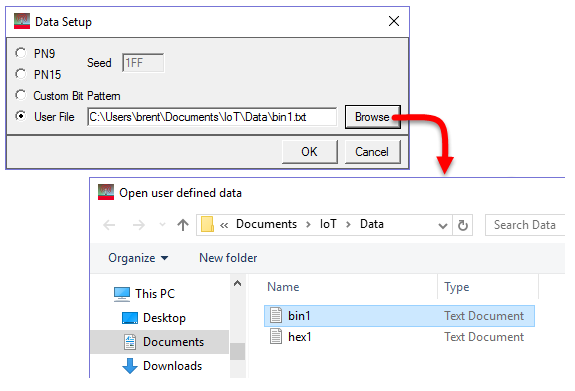
For PN9 and PN15 selections, the Seed field is active and available for use. However, it is inactive (grayed out) for the Custom Bit Pattern and User File selections.
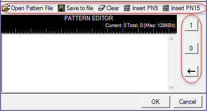
When you select Custom Bit Pattern, the PATTERN EDITOR provides controls (see figure below) for entering and editing data, including loading a previously saved pattern. In addition, there are 1 and 0 buttons for adding single bits. The keyboard may also be used to enter 1 and 0 values. The software remembers the current Custom Bit Pattern within a software session. That is, if another data type is selected and used, and then Custom Bit Pattern is reselected, the editor shows the previously entered custom pattern. If you click Clear, however, the custom pattern cannot be retrieved.
The User File selection lets you load a text file of either binary or hexadecimal data. Click Browse to open the "Open user defined data" window to select a file. The file path appears in the User File field.
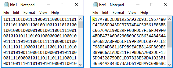
The software accepts two types of user data: binary and hexadecimal. The following figure shows an example of each data type. As shown, the hexadecimal data must begin with an 'x' to indicate hexadecimal data. The 'x' can be either upper or lower case.
Range: 0–2047 Octet(s)
Default: 1024
Enter the length of MAC payload in octets.
When you turn off MAC FCS, the Data Length is the same as Frame Length. When you turn on MAC FCS, the Data Length equals the Frame Length minus FCS length.
Choices: Continuous | Truncated
Default: Continuous
Select the data mode applied to MAC payload for a multi-frame waveform. Continuous mode will have data bits continuously distributed across multi-frame. Truncated mode will have the same payload data bits for all the frames, with the data size truncated for one frame.
Choices: On | Off
Default: On
Enable or disable MAC FCS in the PSDU. When turned off, it can be used to simulate an invalid FCS case, since FCS part is actually filled with user data bits. See Figure 7-1 in IEEE Std 802.15.4-2015 for details.
Range: –300 to 300 ppm
Default: 0
Enter the shift to the standard symbol rate in ppm. This error will be added to standard sample clock in the waveform header.
Range: –200 to 200 kHz
Default: 0
Enter the offset to the nominal carrier frequency in Hz.
Range: 50–150%
Default: 100%
Enter the additional scaling to the nominal FSK frequency deviation. This is equivalent to apply scaling to FSK modulation index.
Range: 0.1–1.0
Default: 0.5
Enter the BT product of the Gaussian filter applied to FSK modulation.